Function Block Diagram (FBD)
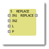
FBD diagram is built of components displayed on a scheme with rectangles. POU inputs are displayed on the left of rectangle, outputs are on the right. Inside the rectangle, POU type and input/output names are specified. For function block instance, its name is specified above the rectangle. Program execution on FBD is implemented according to order specified in upper right block angle. Rectangle size depends on input and output count. It's automatically set by the graphic editor:

Connection Lines
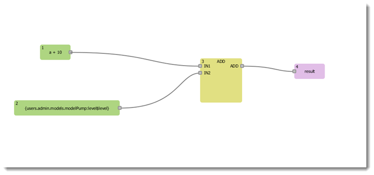
POU rectangles are linked by connection lines in FBD. The connections are directed from the left to the right. Block input can be connected to block output located on the left of it. Besides, input can be connected to variable or constant. The connection should link variables, inputs and outputs of the same type. The width of connection line doesn't matter in FBD.
ST Expressions in FDB
There is also possibility of recording ST expressions at graphic block input. Such a technique expands standard FBD and turns out to be more convenient. Compact expression representation form facilitates function diagram reading and recording.

Labels, Transitions, and Return
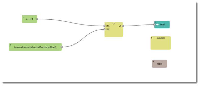
FBD block execution order can be forcibly changed by using labels and transitions. Graphics editor enumerates blocks automatically. The transition is necessarily connected to the Boolean variable and executed if the expression is true. Labels and transitions are displayed in the following picture:

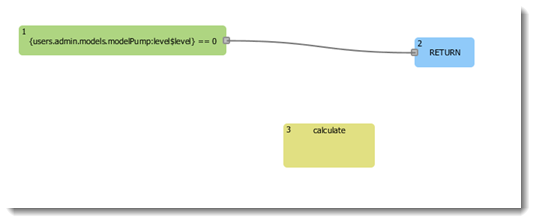
Return operator RETURN is used as well as moving to label, i.e. linked to Boolean variable:

Was this page helpful?