Ladder Diagram (LD)
The Ladder Diagram is also a graphics oriented programming language which approaches the structure of an electric circuit.
The Ladder Diagram is suitable for constructing logical switches, from other side you can easily create complicated networks as in FBD. Therefore the LD is very useful for controlling the call of other POUs.
The Ladder Diagram is a vertical power bus, which is always in the "ON" state. On the right there is a circuit diagram made up of contacts, coils, and connecting lines. The amount of contacts and coils may vary. If contacts connected in series are locked, the current is in the circuit and the coil is "ON". If necessary, several coils can be enabled.
Each contact is associated with a Boolean variable. If this variable is TRUE, then the condition is passed from the left to the right along the connecting line. Otherwise, the right connection receives the "OFF" value. The name of the variable or an expression is written above the contact.
Series connection of contacts or circuits is equal to logical AND operation. Parallel connection is equal to logical OR. A circuit can be closed ("ON") or open ("OFF"). It corresponds to the Boolean variable of the coil (TRUE and FALSE).

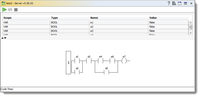
The above diagram is an equivalent to the expression:
 |
|
Contacts
Contacts are represented by two parallel lines: | |, which from the left to the right show the condition ("ON" or "OFF"). These conditions correspond to the Boolean values TRUE and FALSE.
A Boolean variable is associated with each contact. If this variable is TRUE, then the condition is passed on by the connecting line from the left to the right. Otherwise the right connection receives the value "OFF".
Contacts can be connected in parallel. One of the parallel branches must transmit the value "ON" so that the parallel branch transmits the value "ON". Or contacts can be connected in series. Then contacts must transmit the condition "ON" so that the last contact transmits the "ON" condition. This therefore corresponds to an electric parallel or series circuit.
Type of Contacts
Type | Symbol | Description |
Normally open contact |
| The state of the left link is copied to the right link if the state of the associated Boolean variable is TRUE. Otherwise, the state of the right link is OFF. |
Normally closed contact |
| The state of the left link is copied to the right link if the state of the associated Boolean variable is FALSE. Otherwise, the state of the right link is OFF. |
Negative transition-sensing contact |
| The state of the right link is ON from one evaluation of this element to the next when a transition of the associated variable from TRUE to FALSE is sensed at the same time that the state of the left link is ON. The state of the right link will be OFF at all other times. |
Positive transition-sensing contact |
| The state of the right link is ON from one evaluation of this element to the next when a transition of the associated variable from FALSE to TRUE is sensed at the same time that the state of the left link is ON. The state of the right link will be OFF at all other times. |
Coils
On the right side of a network in LD there can be any number of so-called coils which are represented by parentheses:( ). A coil transmits the value of the connections from left to right and copies it to a corresponding Boolean variable. At the entry line the value ON (corresponds to the Boolean variable TRUE) or the value OFF (corresponding to FALSE) can be present.
Types of Coils
Type | Symbol | Description |
Coil |
| The state of the left link is copied to the associated Boolean variable and to the right link. |
Negated coil |
| The state of the left link is copied to the right link. The inverse of the state of the left link is copied to the associated Boolean variable, that is, if the state of the left link is OFF, then the state of the associated variable is TRUE, and vice versa. |
Negative transition-sensing coil |
| The state of the associated Boolean variable is TRUE from one evaluation of this element to the next when a transition of the left link from ON to OFF is sensed. The state of the left link is always copied to the right link. |
Positive transition-sensing coil |
| The state of the associated Boolean variable is TRUE from one evaluation of this element to the next when a transition of the left link from OFF to ON is sensed. The state of the left link is always copied to the right link. |
Reset (unlatch) coil |
| The associated Boolean variable is reset to the FALSE state when the left link is in the ON state, and remains reset until set by a SET coil. |
Set (latch) coil |
| The associated Boolean variable is set to the TRUE state when the left link is in the ON state, and remains set until reset by a RESET coil. |
Function and Function Blocks in the Ladder Diagram
Along with contacts and coils you can also enter function, function blocks. Function blocks must have an input and an output with Boolean values and can be used at the same places as contacts.
Order of Network Execution
The Ladder Diagram means a parallel operation of the circuits. Electric current is transmitted to all the circuits simultaneously. As for Ladder Diagram (LD), it is executed sequentially from left to right, and from top to bottom. In every runtime, all the LD circuits are executed once, thus creating a parallel operation effect. Within one circuit, any variable always has a fixed value. Even if the coil changes its variable, a new value is transmitted to the contacts only when a new runtime starts.
Circuits located below get a new value at once. Circuits located above obtain it in the next cycle. It is crucial to stick to a strict procedure of the execution. A random or truly parallel order of the circuit execution could lead to the "race effect" which happens in electronic circuits with triggers. Due to a strict order of the execution, an LD maintains stability when having a feedback path.
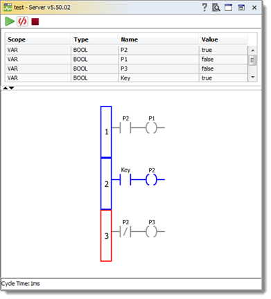
As it is mapped in the flow chart below, as soon as the Key variable is TRUE, it sets the P2 variable to TRUE and P3 to FALSE (in the same cycle). P1 relay will be set to TRUE in the next cycle, even if the Key is set to FALSE:

Control of Network Execution Order
It is possible to change the execution order of the diagram circuits with the help of jumps. A jump is equal to an output coil and executed if the output variable is set to TRUE. A jump is placed at the beginning of the circuit (its number is given in a jump). Using a jump, you can skip the execution of a part of the diagram. Skipped circuits are not reset. Not being executed, they just pause. It is allowed to set a jump up and create a new cycle. A software engineer is responsible for checking the conditions of the end of the cycle. The RETURN operator terminates the LD execution. If the main program contains the RETURN operator, a working cycle breaks. As for functions and function blocks, it returns to the call place. In other words, the RETURN jump acts the way the RETURN operator does in textual languages.
Was this page helpful?


