Implementing Data Models
A series of models will be created based on the abstract model developed during the analysis of the elements of the power generation system. An Absolute Model will be used to model data not connected with a specific device such as Illuminance, Day Length, and Expected Output Power. Instantiable Models will be used for each type of device, including Transformer, Inverter, and Solar Panel, as multiple instances of each type will be connected to the system.
After the models are created, specific instances for each device in the system will be created, and options for populating the model instances with data will be considered.
Creating Absolute Models
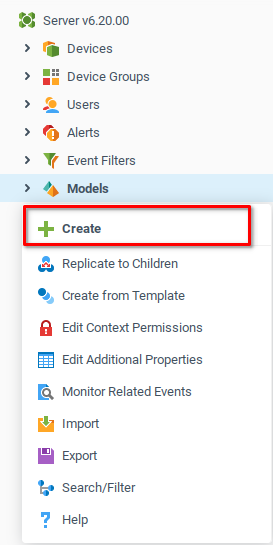
Start by navigating to the System Tree and opening the context menu for Models, and choosing Create.
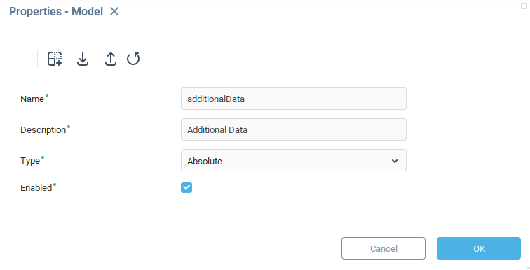
The model properties window gives you the option to enter identifying information about the model. Set the Name to additionalData and the Description to Additional Data. When retrieving data from this model programmatically via the expression language the name additionalData will be used, and the description Additional Data will be displayed in the user interface.
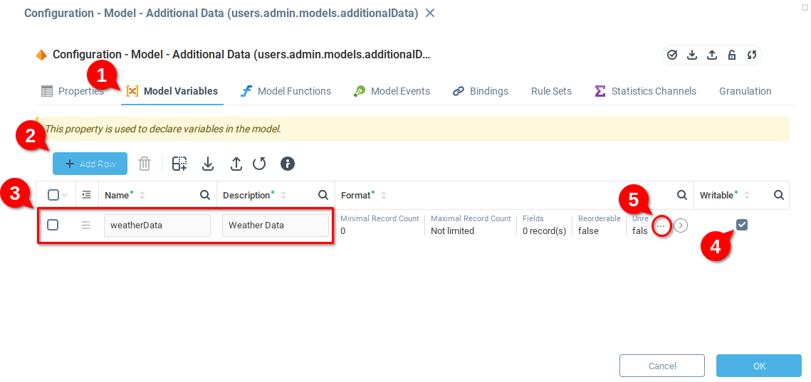
Clicking OK creates the model and opens the configuration window where you can set a number of parameters. To create a few variables, Select the Model Variables (1) tab and choose Add Row (2).
Add an appropriate Name and Description (3) and make the variable Writable (4).
In the example, the variable is named weatherData which will be the name of a tab in the model which will eventually be a collection of several weather-related variables.
Finally, open the Format field (5) which opens the Format menu.
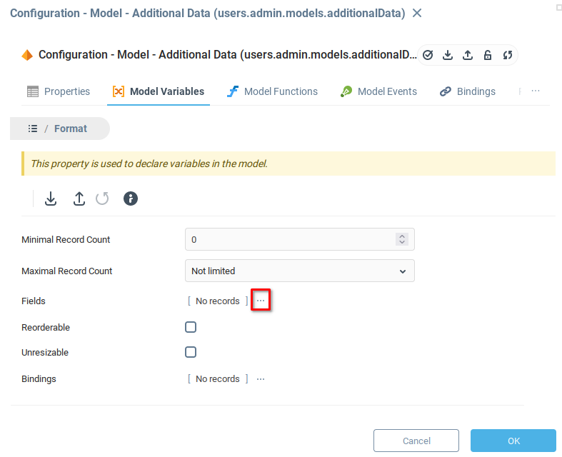
The Format menu has a number of options, but at this stage you only need to define the Fields. Open the Fields menu by clicking on the icon indicated below.
The Fields menu allows for any number of variables to be created by clicking the Add Row button. The example contains two variables cloudCover and illuminance which are both defined as integers.

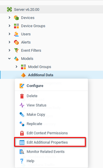
Save the changes and close the window by clicking OK. In the system tree, you should see the new model Additional Data under the Models node. Choose the Additional Properties item from the context menu to display the variables associated with this model.
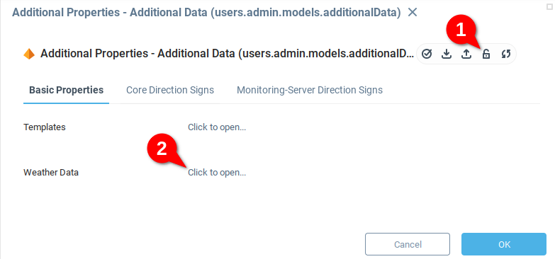
In the Additional Data menu, locate the model variable Weather Data. Later sections will explore methods of automatically populating variables with data. To manually edit the values of the model, first click the lock icon (1) and then open the Weather Data variable (2).
The Weather Data panel opens a Data Table Editor which allows variable values to be manually entered by clicking Add Row and then providing values in each field.

You may find that additional variables are needed as the complexity of your system model grows. Absolute models are useful for storing variables which are at a high level of abstraction in your system or synthesized from a number of sources.
Instantiable Models
Consider the case of the power plant where there are multiple similar devices, each with the same types of associated variables. Rather than creating an absolute model for every device, we will create instantiable models. An instantiable model serves as a template which defines the variables, functions, and events which will be associated with each instance of the model. Then we create a unique instance of the model for each device.
As with creating an abstract model, open the context menu for the Models node in the system tree and choose Create.

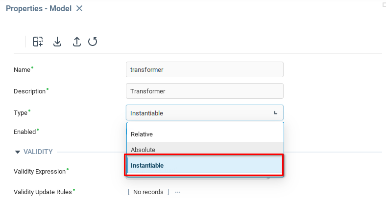
From the properties window, add an appropriate name and description and set the Type as Instantiable.
Notice that several properties appear which are specific to instantiable models. Model instance containers can be attached to almost any context. The model Validity Expression is evaluated for each context in the server context tree, and if it results in True, a container for the model's instances is attached to the context.
In order to make the Transformer devices available in the root context, set the Validity Expression to {.:#type}=="root". Later on we will look at how the Validity Expression can be used to create nested devices hierarchies with nested containers.
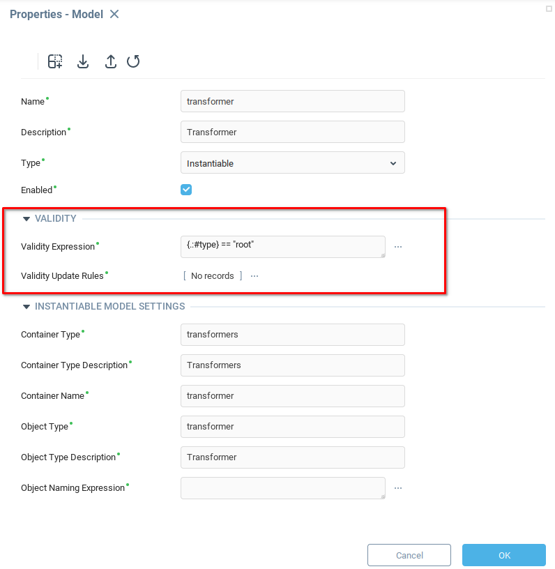
The parameters under Instantiable Model Settings control the names and descriptions of containers and model instances. The article configuring model instances and their containers provides detail about the different options.
As in the example below, set appropriate names for the containers and objects based on the word “transformer”.
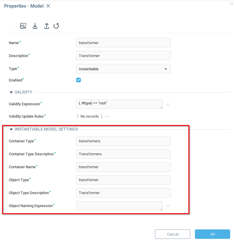
After filling in the names and descriptions, click OK to save the model and open its Configuration window.
Object Variables
Similar to an absolute model, create variables from the Model Variables tab (1) by adding a row (2), providing a name and description (3), making the variable writable by checking the appropriate box (4) and then opening the Format menu (5).
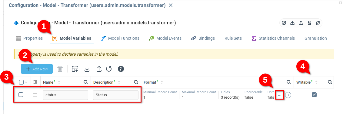
Under the status heading, create at least two variables, Device Status and Current Power Output. Since the device can only have one value for Device Status and one value for Current Output Power at any given time, limit the number of rows which can be in the status variable by setting the Maximal Record Count (1) to 1 and then opening the Fields menu (2).
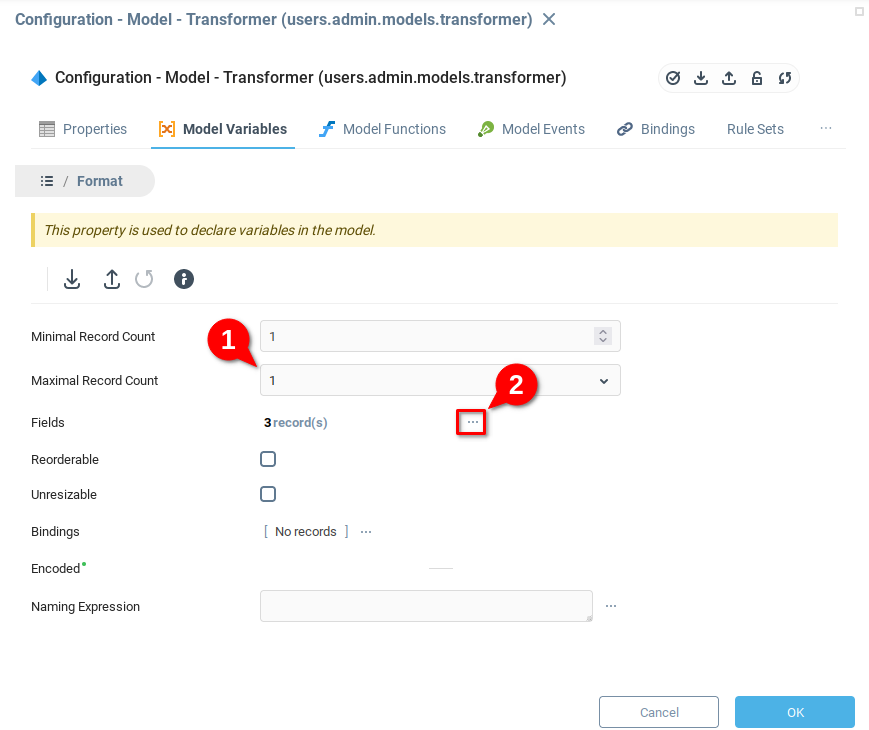
Add two fields to the list deviceStatus and currentOutputPower. Note that in the example the Type of deviceStatus is set to Boolean and indicates a default value of True.

Click OK to close and save the variables. At the bottom of the system tree, you should see that a container Transformers has appeared.
Creating Model Instances
Now that the model has been created, model instances can be created. Navigate to the bottom of the system tree, open the context menu for the Transformers node and choose Create.
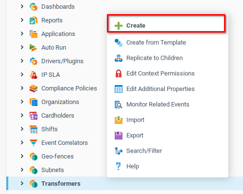
Creating a model instance opens the Object Properties window, where the new Transformer instance can be named. In the below example, the transformer is named a since the physical object represented by this instance is “Transformer A”. The model container is named transformers, therefore this instance will have context path
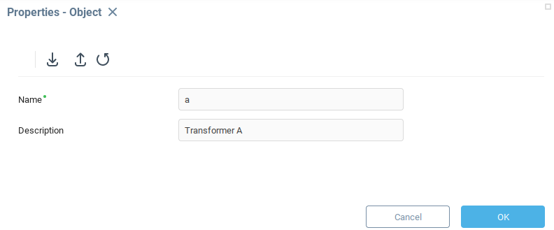
Naming and saving the new object opens the Object Configuration window. Recalling the variable status in the model, navigate to the Status tab (1) and check that the fields deviceStatus and currentOutputPower variables exist in the model instance.
The user interface automatically displays these as single variables listed horizontally rather than a table because the minimum and maximum number of rows of the data table was set to 1 when the status variable was defined in the model.

Manually add some data if desired, and then close and save the instance. In the example, another transformer was added to more accurately model the power station, creating an instance named Transformer B.
Creating a Hierarchical Device Model
Having created an instantiable model and a few instances of that model, now look at creating a device hierarchy. Recalling the power station device topology, each transformer draws power from several inverters, and each inverter draws power from several photovoltaic arrays.
To model this hierarchy, the following will show how to create a model instance Inverter which will be attached to instances of the Transformer model, and a Panel model which attaches to instances of the Inverter model.
To start, create another Instantiable Model by choosing Create from the Models context menu. This will be the Inverter model. To attach these instances to the Transformer model, the Validity Expression must be defined as {.:#type} == "transformer". This expression ensures that the container for Inverter instances will be connected only to Transformer instances.
Note that the properties for Instantiable Model Settings are populated with appropriate values for an inverter device.
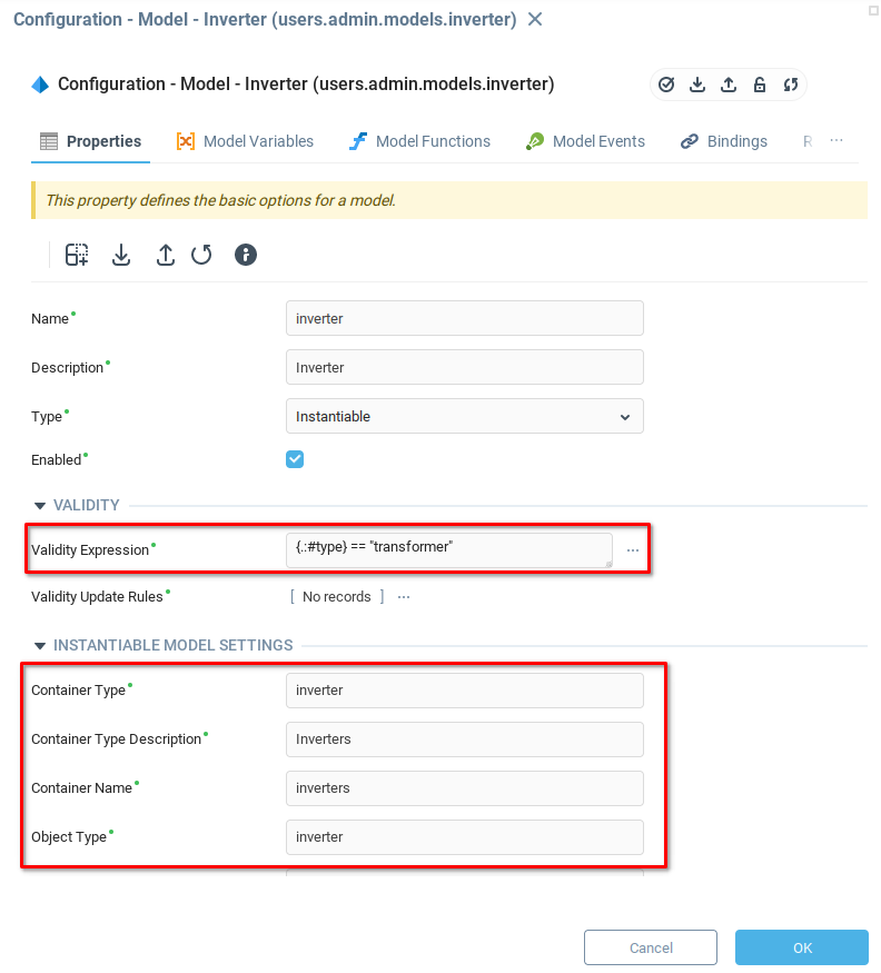
Having defined the parameters for the model containers and object, navigate to the Model Variables tab, and add a writable status variable.
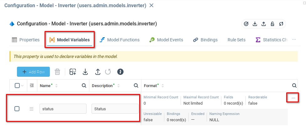
As with the Transformer status variable, set Minimal and Maximal Record Counts to one and then open the Fields table.
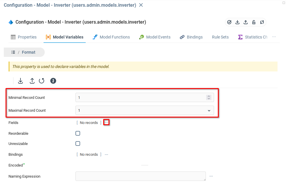
Create a few variables for the Inverter model. The example includes the following variables:
Cabinet Temperature, Integer
Inverter Efficiency, Integer
Output Power, Float
Active Status , Boolean

Having saved and closed the model configuration page for the Inverter, click the Transformers node in the system tree to reveal the Transformer model instances. Clicking a Transformer instance now reveals the Inverters container.
Open the context menu for the Inverters container and Create a new instance.

Similar to the Transformer model, add a name and description to the new instance, and click OK.

After creating a new instance, the configuration window should open. Navigate to the Status tab to confirm the presence of the variables that were added to the model in the previous steps.

The above example contains some data which was entered manually. We will look at populating model data in another chapter.
Add Model to Represent Panels
In the power station example, another instantiable model of type panel, nested under the inverter type models was added. Recalling the previous step, the Validity Expression for an instantiable model attached to inverter type models is {.:#type} == "inverter".
The Panel instantiable model also has a status variable with two fields, activeStatus and outputPower, respectively of Boolean and Float type.
In the system tree, under each Inverter instance, you see a Panel container, allowing Panel instances to be added to each Inverter.

You may want to conclude this exercise by considering what additional model instances are needed to complete the digital representation of your system.
Using a Versioning System
Now that you have an understanding of the basic use of models, the next step is to look at how to package a series of models into an application, manage application development with a version control system, and share applications with users.
Was this page helpful?