Using Custom Images on Maps
Iotellect Server supports adding your own images on maps. This article describes how configure a dashboard to use custom SVG images on a map.
Adding Custom Non-Standard Images Into Device Images Model
 |
|
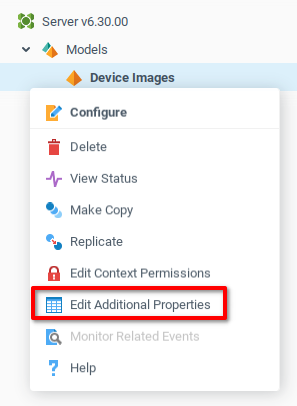
Expand the Models container in the System Tree. Right click on the Device Images model, and choose Edit Additional Properties.
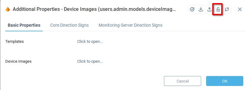
Disable read-only mode by clicking the lock icon.
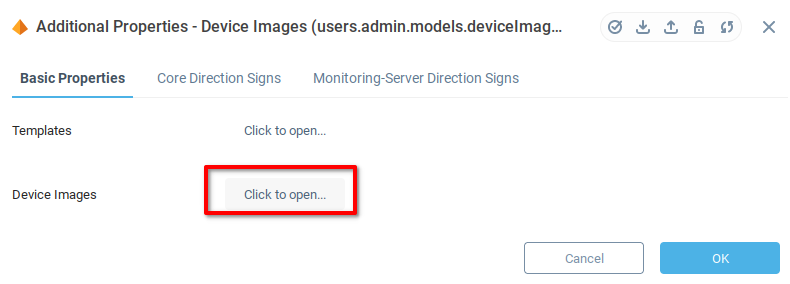
Click on the Click to open... button of Device Images and add your own SVG image using the Add Row button ( ) specifying the image name.
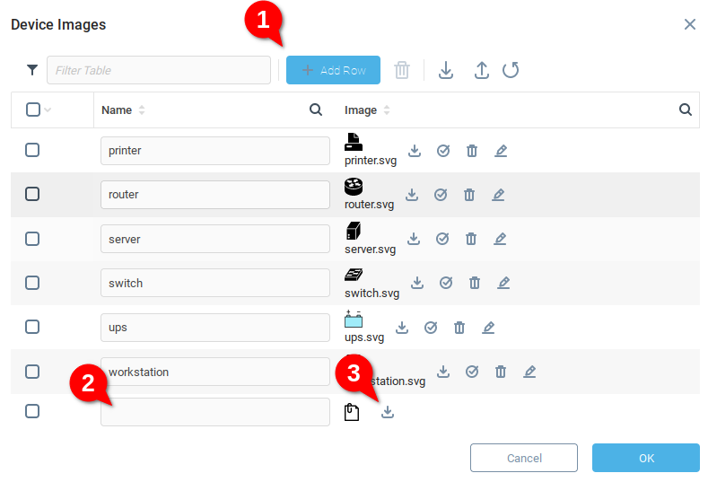
From the Device Images window, a new image can be added by adding a row (1) giving a name to the device (2) and uploading an appropriate image (3).
The following example will use the image named server.
Add a Custom Device Type to all Devices with a Relative Model
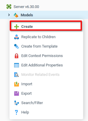
Create a new model by choosing Create from the context menu of the Model container.
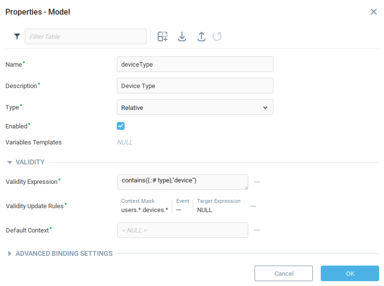
Create the model with the properties indicated in the following table:
Property | Value | Notes |
|---|---|---|
Name |
| The name of the model used when forming the context path. |
Description |
| Description of the model appearing in the user interface. |
Type |
| Type of model. Relative models can be “attached” to other contexts according to the Validity Rule. |
| Determines which contexts this relative model will be attached to. | |
| Indicates the conditions under which the validity expression will be reevaluated. |
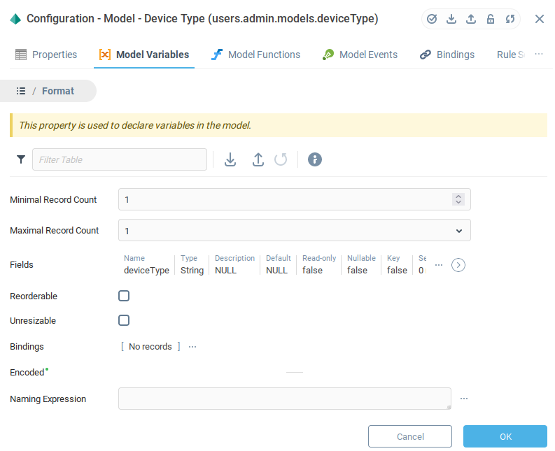
Click OK to save and open the Model Configuration window. Navigate to the Model Variables tab (1) and click Add Row (2). Enter the data indicated in the following table (3), and then open the Format Field (4).
Field | Value | Description |
|---|---|---|
Name |
| |
Description |
| |
Writable |
|

From the Format menu, configure the variable format with the following data:
Property | Value | Description |
|---|---|---|
Minimal Record Count |
| Since the variable table should have one row and one column., set this to |
Maximal Record Count |
| Since the variable table should have one row and one column., set this to |
Fields |
| Define the data type of the variable as a string. |
Click OK to save and close.
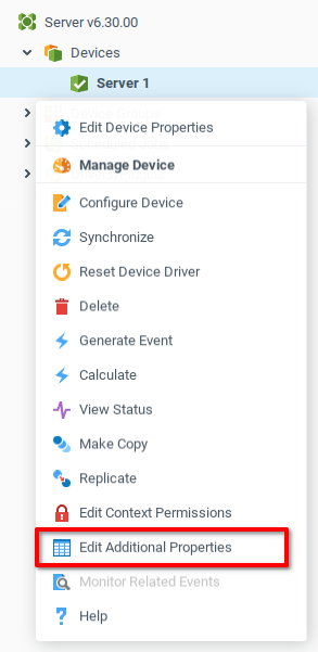
Choose a device from the Devices context to assign a type. In this example, there is a virtual device named Server 1 already created. Open the context menu for the device and choose Edit Additional Properties.
Navigate to the Device Type tab of the device (1), toggle write mode (2) and indicate a name for the device.

Click OK to save and close.
Specifying Device Coordinates
In order to display the device on a map, specify its latitude and longitude. From the device context menu, choose Edit Device Properties. In the Generic Device Properties tab, enter a value for the Latitude Expression and Longitude Expression.
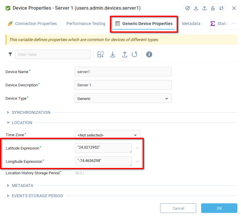
Press OK button to save and close.
Repeat the process of adding Latitude and Longitude expressions for every device that must be included on the map.
Creating a Dashboard with Map Component
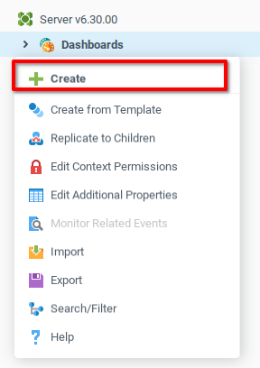
Click Create from the dashboard context menu.
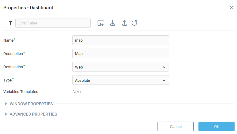
Fill in the Name and Description fields and click OK. In the example below, the dashboard name and description are Map.
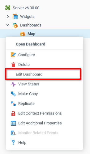
From the newly created dashboard context menu, click Edit Dashboard to open the Web UI Builder.
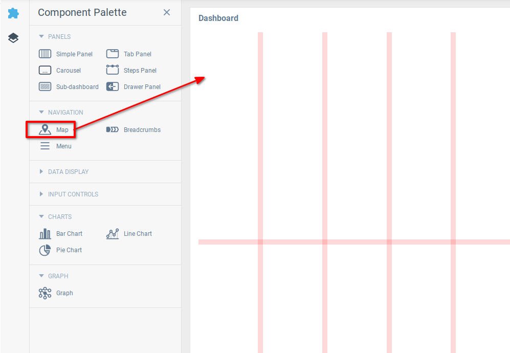
In the Web UI Builder, drag and drop the Map component from the Component Palette onto the grid.
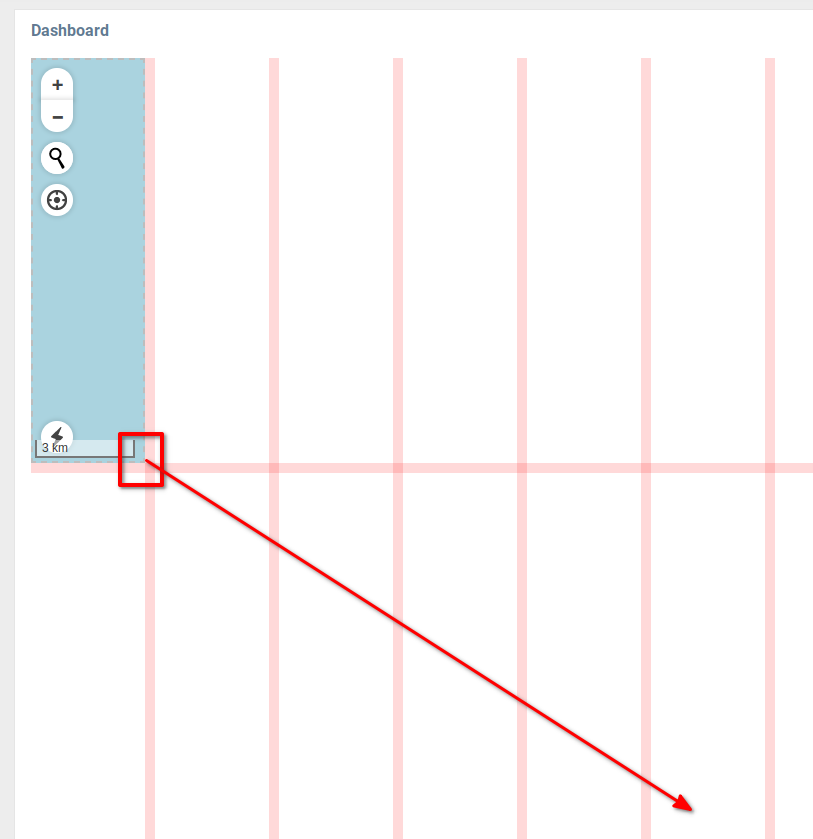
Drag the lower-right corner of the map component to expand the amount of the screen it covers.
Adding Markers to the Map
A marker can be placed on a point in a map by indicating a latitude and longitude. Each marker must be placed in a layer. The following steps create a layer, place a marker in the layer representing the device Server 1, and then load the custom an image with the layer.
Create Layer
Open the Map Properties Editor, and then open the Layers property for editing.
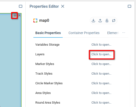
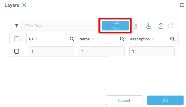
Add a single layer to the map by clicking Add Row and adding the indicated data.
Field | Value | Description |
|---|---|---|
ID |
| This is the layer ID to which any associated markers must refer. |
Name |
| Name when referencing the layer in the expression language. |
Description |
| Layer description which will be shown in the user interface. |
Create Marker from Device
Markers will be created using component bindings, since they should update automatically according to changes in the device. From the Map Properties Editor, open the bindings for Markers.
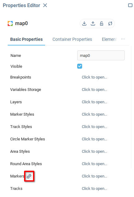
From the Bind Property menu, create a new binding with the following data:
Property | Value | Notes |
|---|---|---|
Target |
| This is the target, in this case the table container all markers. |
Expression | addRecords( {form/map0:markers}, | We add records to the Markers table
|
On Startup |
| Set to true to activate the binding when the dashboard is loaded |
Style Marker with Custom Image
In a similar way as above, open the Marker Styles bindings and add the following data
Property | Value | Notes |
|---|---|---|
Target |
| This is the target, in this case the table containing marker styles. |
Expression | addRecords( {form/map0:markerStyles}, | We add records to the Marker Styles table
|
On Startup |
| Set to true to activate the binding when the dashboard is loaded. |
Viewing the Result
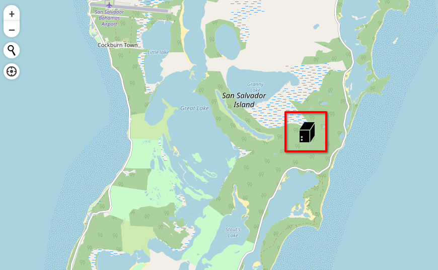
Finally, launch the dashboard and view the result. Navigate to the latitude and longitude specified for the device. In our case, we see the server located in San Salvador Island of the Bahamas.
Was this page helpful?